FREQUENTLY
ASKED QUESTIONS ABOUT GRAMPIAN 26
BACK
to G26 Page
F.A.Q Index Page
I will be
keeping an eye on the other Grampian Forums and adding here any interesting
information regarding repair and maintenance from these other sites plus any
information you want to provide on "fixes" you have made to your
Grampian that others might find of interest. Please contact the
Webmaster
with any suggestions.
-
What is
the length of the Shrouds on a Grampian 26?
-
I want
to redo my windows. Where can I get the grey gasket?
-
How do I replace
my Windows?
-
How can
I unstick my centreboard? Update
-
Tightening Keel
Bolts
-
Rudder Problems
-
More Rudder Questions
-
Tiller Handle
Replacement
-
Steel Cradle
Dimensions
-
How can I prevent Mast
Compression?
-
How do I step/unstep
my mast if no crane available?
-
How do I replace my bulkheads?
-
How do I repair/replace a broken mast step hinge?
-
Wiring Problems - Questions and Solutions
-
Forestay Fitting
Failure
-
Replacing Floor
Supports
-
Can I sail
OK with my C/B stuck in the up position?
-
Replacing
the original burlap covering on the walls
-
Installing
Toe-Rail Mounted Stanchion Bases
-
Rudder Retaining Pin
-
Where to Position Jib Blocks
-
Handrails
-
Sloppy Rudder Play
- What is the
length of the Shrouds on a Grampian 26?
Every boat is a little
different and it is recommended that if you are replacing any of your
shrouds, you take them off and send them to the person who is making the new
ones. They can then get an exact measurement of your existing shrouds and
cut the new ones accordingly. half an inch can make a big difference!
(Back)
- I want to
redo my windows. Where can I get the grey gasket?
The gray gasket can
be obtained from Holland Marine Products
(Back)
- How do I replace my windows?
See
F.A.Q. on General F.A.Q. Page
- How can I unstick my
centreboard?
Nothing I tried would unstick the
centerboard. So I went the 'foolproof' way.
- First you have to be able to access the trunk. To that effect the keel is
sitting on a wooden cradle that raises it above the bottom of the steel cradle.
The wooden cradle is made of two rows of stacked 4"x6" separated
by a 3" space. It is held together at the endsso has not to separate
.It has 'windows' at various points to be able to put in a hand and reach
the underside of the keel. The 3" space allows the centerboard to fall
through it. Since the steel cradle is held by cement blocks I could manage
to slip under the steel cradle and reach trough the wooden cradle's space up
to the keel trunk.
- Second, I made a U shaped bracket out of thin steel tape ( the kind used
to hold water pipe with holes in it ). I managed to wiggle this contraption
so that it caught the end of the centerboard inside the trunk. This
confirmed that there was enough space between the centerboard and the trunk
at the end of the centerboard to wiggle a "U" bracket over the
centerboard. This bracket could then be hooked to a cable and pulled at 90
degrees trough a pulley attached to a cross beam of the steel cradle
-In my case I first tried to pull the cable which was in fact a 1/2"
sheet line with a ratchet capable of exerting a one ton force.
- This was not enough, the steel
tape stretched, the line also and nothing moved.
- I then went the hard way and built a "U " bracket made out of
heavier steel. This bracket could not pass at the end of the centerboard as
there was not enough space between it and the trunk. To allow this bracket
to 'snare' the centerboard I had to remove 1/2" at the end of the
centerboard with a special long shaft air die grinder fitted with a 6"
carbide burr.
- Then using 1/4" aluminum aircraft cable and heavy duty pulley and two
4 ton hydraulic jacks I was able to free the damn thing.
If you are lucky you may not have
to resort to as much force as I did.
I was able to see from the marks on
the board that there are some sort of bumps inside the trunk which dug
inside the board near the end and on one side.
ThIs spring I will undertake the
cleaning and I have built a special rig to 'ream" the inside of the
trunk with the air tool fitted either with a wire brush or carbide burr. I
do not know yet if it will work.
I will then paint the inside with
POR-15
In the meantime I will repair
the board which is a sandwich of fiberglass and steel and I will drill a
hole in the steel at the leading hedge of the board so that in the future if
it get stuck again I will be able to easily 'snare' the board.
(Courtesy "romarin11")
When I bought my
boat it was up on wooden beams spread across upright 55 gallon drums. The
centerboard was out of the boat, and the hinge mechanism long gone. The cb
was stripped of fiberglass; just the 1/4" steel plate remained. The
original mechanism for the cb consisted of an inverted U shaped aluminum
bracket with little 'feet' at the bottom of the legs of the bracket. Imagine
the cb in it's retracted position, with this bracket straddling it near the
head, with a pin going through the cb to swivel it.
The 'feet' had
holes drilled through them so that the entire assembly (bracket and cb)
could be pushed up into the keel(after attaching the cable) and bolted on to
the bottom of the keel. If you look hard you can find some notches about 1/3
of the way aft on the keel's bottom edge. There are screw holes tapped into
the keel in those notches for the cb assembly, the 'feet' fit flush to
reduce drag. Most G23's have these notches glassed over when the cb is
abandoned.
Now, let's get
back to the real world! I tried to design that assembly from scratch. That's
just plain nuts. Instead, I figured out the swivel point and drilled a 5/8"
hole straight through the keel(took forever!) and then epoxied a 1/2"
stainless pin in place. First I re-glassed the cb and drilled it, too, of
course.
It was a pain,
but I had sailed the boat w/out the cb for a few years and wasn't happy with
it's pointing. It is so much better now! (Bill Bairley)
(Back)
______________
Here is a Forum
thread about repairing G26 Centreboards
http://www.anything-sailing.com/showthread.php/6221-Grampian-26-centerboard
- Tightening Keel
Bolts
I spoke to Gill Bibby a few
weeks ago on a survey. (Gill was the production manager at Grampian.)
At the time he had suggested snugging the keelbolts. He said on the
G26 the keel bolts were 1" threaded rod and since the keel is cast
iron, you can torque them all you want without the danger of pulling the
threads in the keel.
A 1" thread has a nut 1-1/2" across.
Let's assume the threaded rod material used by Grampian corresponded to the
SAE Grade 2 specification, the basic level of hardware store quality
bolts. A 1"-8 UNC thread will take a maximum torque of 300
ft-lbs, and give a clamping force of about 18,000 pounds in that joint.
(300 ft-lbs should be
about 400 N-m)
That is, fully torqued, it would take an 18,000 pound pull on each bolt
before the hull-keel joint would start to open. Less torque gives a
proportionally smaller amount of load to cause the joint to separate, but
you can see there's a lot of leeway here.
Personally, I'm going to suggest that 300 ft-lbs is a _lot_ of torque, and
even a third of this will be plenty. It's also a lot easier on the guy
turning the wrench. (Thanks to Tim Nye in conversation with Gill Bibby)
(Back)
-
Rudder
Problems
One thing I can mention is on wet
rudders. Gill said they produced the rudders (at least on the G26)
with the stainless rudderpost that was drilled through with 1/2" holes.
They inserted 1/2" stainless rods that were bent into a curved shape,
so you'd have a structure like fishbones. This was then encased in the
rudder shells and filled with resin.
He didn't recommend cutting a wet rudder apart and rebuilding it.
There can be some space inside, and water can leak down the side of the
rudderpost. He suggested you store the rudder upside down in a warm
place over the winter, to let any water drain and dry out. Then put
the rudder back right side up and build a dam around the rudderpost with
masking tape. Mix some slow setting epoxy (2-3 hours), pour it into
the dam, and let it slowly seep into the rudder. When it hardens, it
fills the voids in the rudder, and hopefully, seals the gap around the
rudderpost. (Thanks to Tim Nye in conversation with Gill Bibby)
Jimmy Schools had a good description
of how he fixed his rudder after the shaft was accidentally bent but the
site it was on no longer exists. I am attempting to obtain a copy but in the
meantime I do have these photos of his work that someone sent me


.
The following are comments received
concerning Jimmy's bent rudder and his subsequent repairs:
"Let me say first that I am not an
expert, so the following opinion could very well be wrong.
What stands out for me in the photo is
the diameter of the shaft is considerably reduced just above the top of the
rudder, where the bend is. We have a 1973 G26 that's been primarily in Lake
Ontario and the NY Finger Lakes over its life, and there is no noticeable
wear on the diameter of the shaft. You can see how much more wear is on your
shaft at the bottom bearing than the top, and the rusty appearance, which
makes me suspect that this shaft may have been going through a crevice
corrosion process.
If this is the case, no doubt the
metal of the shaft will have deteriorated where it enters the rudder (where
most of the bending has occurred). So the shaft could be greatly weakened by
corrosion, and further weakened by being bent so much. Bending it back would
cause more damage to the shaft, and if the shaft didn't break then, there
could be small cracks left that would grow over time until the rudder does
separate. Of course, this would happen when the rudder is most heavily
loaded, which is the worst time to lose it.
Personally, I'd want to open it up and
redo any damaged material.
I'd also closely inspect the rudder
tube and hull attachments for any damage. Bending a big (inch and three
eighths?) stainless shaft like this takes a lot of force." (Tim Nye)
"I did bend my rudder shaft two years
ago and was able to straighten by strapping the rudder down to an I beam
(big boat trailer) and using a long pipe that fit over the shaft (6-7 foot
pipe). I bent it back by hand but my shaft was only bent about 5-7 degrees.
Yours is considerably worse. I would check with someone regarding whether
it’s even wise to bend something back from that angle. There maybe some
issue with metal fatigue." (Todd Dupuis)
I had a rudder incident, which caused me to
have to create a rudder with no pattern to go by!!! My rudder broke off
and fell to the bottom about five miles out!
One of the pics is the new creation with
my own size dreamed up from some research.


The rudder dimensions pic is something sent to me by the
owner of a G 30.
Mine is a G26. The new rudder handles the boat
200% better than the original. Made completely of stainless steel 1/4 "
plate with a 1" shaft. A local guy who does prop reconditioning and shaft
straightening did the work. The shaft is what he called Aqua steel grade
stainless. And the plate is a grade sufficient to not rust in salt water.
I installed it myself while in the water. A bit tricky but I have a great
helper in my wife. Your fabricator will be able to recreate the
configuration you need at the top to reconnect to the tiller mounting
gear. I used a 1.5" brass spacer with a setscrew right at the deck surface
to sit on top of the brass washer that lay on the deck.
Between the rudder blade and bottom of the boat
I put in a large stainless washer as a protector from the blade to the
hull. If you end up sitting on bottom the blade shouldn't dig into the
bottom.
Even though this has been an experimental
project I feel it is a substantial long-term fix. I will likely shave some
of the bottom off the rudder in the future as I have discovered that the
rudder remains the furthest protrusion bottom side. I sail in places where
water can get to 2' near shore and running a ground is a real possibility
For rudder protection I need to be about even
with the keel. I feel the handling will not be compromised if I take a
little off.
Lastly the estimate to have a boat yard do
something for me was $2300. I got all this done for $500 with me being the
handyman project engineer. (Rick Zegel)
There were 2 different designs of this
rudder:
"The shaft could be
3/4 down in the blade and bent aft, then fitted with tangs in which to
hold it in place. The other way the rudders were made was to attach the
shaft to a steel plate that is in the center of the rudder."
Well it certainly makes Grampian
building look good again. The FRP rudder blade did not get damaged in the
impact and I wonder if the the shaft would not have bent if it had not
been worn so badly at the lower bearing point.
The filler in the rudder cavity is
micro balloons, a powder filler mixed with Polyester resin, I would grind
out most off the filler around the shaft location, leaving some location
points for reference when replacing the shaft. Then make a fill of chopped
strand matt and resin, half fill the cavity with this mix and then place
the new shaft in place, fill the remainder of the cavity to the surface of
the rudder skin. Let this harden. Grind off the surface until a slight
dished area is achieved and then lay layers of fibre glass cloth and matt
to replace the skin. This skin must overlap the onto the original skin
some distance. Finally to prevent the patch from letting go, I would sand
the surface of the rudder skin so that a wrap off fibre glass or two can
be applied round the total rudder to bond to the original fibre glass
surface.
The new shaft should be machined while
it is straight, drill for the location pins, install the 1/2" pins and
then bend the pins to the angle required. have the new shaft bent to the
angle required. Note do not machine the worn section back into the shaft
at the top of the rudder, (Dont Laugh, it happens that I have one hanging
in my shop to demonstrate what not to do, it also was bent to match the
old one.) The new shaft could be made from 306 or 312 Stainless Steel.
The best rudders are the earlier ones that were made from a stainless
steel shaft that was bent aft within the rudder casing with two or three
1/2" rod tangs fitted into holes drilled into the shaft, they protruded
aft like a fork. The outer rudder case was laid up in the mold Gel coat
fiber and woven woven, the two halves were filled with micro fibers and
resin paste, place in the shaft in one half and fit the other half on top,
clamp to seal, leave to dry. open the mold and presto you have a rudder.(Thanks
to Gill Bibby)
(Back)
- More Rudder Questions
Question?
Where would
I get bearings for my rudder shaft for my G26 and how
do I get the old ones out?
Suggestions:
There were two designs
used at different times in production.
I seem to recall that one was plastic bushings pressed into the rudder tube
in the hull. In this case you can knock out the old bushings, measure them
and the rudder shaft with a micrometer and check with a bearing distributor
(I've had good luck with Canadian Bearings) to see if they can source an
off-the-shelf replacement.If not, you need to find a machine shop that will
machine replacement bushings for you.
The other design had "gun metal" bushings soldered into the ends of the
rudder tube, which was a piece of copper pipe. This is what our boat has.
The bad news is that to un-solder the bushings, you need to heat the pipe,
and that will destroy the fiberglass that holds it in place.One option is to
remove the old bushings by machining them out, for instance, with a file or
die grinder and burr and a lot of patience, then press or glue in plastic
bushings. Another option is to use an epoxy repair putty like JB Weld or
Devcon putty to build up the inside diameter of the existing bushings, but
you then have to come up with a way to bore the bushings to the right
diameter for the rudder shaft.
I'm afraid that's not a very good answer. Hopefully
someone has a better solution. (Tim Nye) Back
-
Tiller Handle Replacement
While Grampian
tiller handles are pretty substantial, they do get lost, broken or
delaminated. One owner with this problem undertook some substantial
research and developed a process for building a new tiller with the same
dimensions and bend as the original.
Here is the information he has provided. (George Kuipers) (Back)
-
Steel
Cradle Dimensions
Grampian 26 cradle
dimensions. Base 60"x 120" Trough for keel starts 43" from
bow and goes to 25" from the stern. Cross members at 52 " from bow
and 36 from stern. Trough is 8" wide. Uprights are bow
40"tall from top of base, cross member 18" from top. Stern
34" tall , cross member 10" from top.
These were taken from a folding steel cradle ( a common requirement for
cradles in the Toronto area so they can be piled)
These cradles have adjustable pads. The pads should ideally have a range of
4" to 10 ".
(Thanks
to Hans Nita. Info on wooden cradle can be found in G26 owners manual.)
Just a note regarding
the dimensions for the Grampian 26 steel cradle. I built mine using the
dimensions given above but found the bow support to be too wide to allow the
pads to properly contact the sides of the hull. I looked at another cradle
at the club and found that the front (bow) frame should be inset by 6 inches
on each side. Hope this avoids any confusion in future for any one
else contemplating building their own cradle. (Bill Westfall)
(Back)
-
How
can I prevent Mast Compression?
What is mast compression? Some
boats have problems when their rigging is tight that the mast will press
down on the cabin roof and it will be difficult to open and shut doors. This
is especially noticeable if the boat is close hauled with a lot of downward
pressure on the mast.
The previous owner of Patience came
up with a great solution, (he was an ardent racer!). He installed two boards
about 3 1/2" x 1" as beams on either side of the passage between the fore
cabin and the main cabin on the cabin sides. He then installed two braces
for each beam going either from the cabin sole or the seat. This provided
great support directly under the mast. You can see photos of it
here. He just recently told me that he also
installed a longer piece of channel iron that the mast sits in that extends
over both these beams. (I will get better photos this year)
This solution works great and I
never have any mast compression even with a tight rig.
This is an update from the person
who installed this set-up.
One inch thick shaped to fit
deckhead at both bulkheads, both sides, through bolted, plugged both
sides I believe. Wood used was Mahogany.
Uprights same thickness same wood, cut to fit tight to Beams and
taken down as low as possible on bulkhead, both forward and aft
sides of bulkhead. (Depends on boat layout)
Mast step galvanized steel Channel, bore all holes needed in bare
steel then galvanized, also make it long enough to span both
interior bulkheads. That should stiffen it up a bit!!
(Back)
-
How
do I step/unstep my mast if no crane available?
Stepping/unstepping your mast using a crane is the
easiest route but cranes are not always available. Here is one suggestion
for unstepping your mast without a crane but with the help of your club
mates. I am not sure if you work in reverse this will work for stepping but
there are some great ideas to be found if you Google "stepping mast":
I drop my mast every year and the
trick is to have a line attached to the head of the mast to help it down. I
use a fore halyard, some use their fore stay.
Remove all rigging from the tabernacle
so the swing of the step will not have anything to snag and break on. I
release my forward shrouds and loosen my upper & aft shrouds but do not
release them. They will help keep the mast from going sideways.
You should have about 4 other people
to help that means you want at least 5 counting yourself. This makes it
safer. I figure the mast weighs around 250 lbs. I didn't have enough help
the first year and my mast fell on me breaking 2 ribs making my life
miserable for the next couple of weeks and scaring the hell out of me.
One person using the fore line to ease
the mast back, I hook it under a cleat on the dock to act as a break and I
make the angle as much as my line will allow.
2 on the coach top to start the lean
and steady it as it comes down.
2 in the cockpit to take the mast as
it lands The fore line is taking a lot of the weight in the beginning and is
a real help most of the way down. The people on the roof will be taking some
weight before the other 2 in the cockpit can help. A couple of solid planks
across the seat would help the cockpit crew to assist the 2 on the coach
house sooner.
This system works well for me and
about 50 other boats in our club.(Thanks to Brian Lumley for this)
1) I had an 8' 2x4 that I cut V-notches into either end to make a
gin-pole, with one end to rest against the mast, and the other for the
rope/forestay. 10' or 12' would have worked better.
2) The lower shrouds were disconnected and the upper shroud turnbuckles
loosened. The pivot bolt on the mast step was loosened.
3) The companion way hatch was closed and a big block of structural foam
set down for the mast to rest on when it was horizontal.
4) Disconnected the forestay from the bow fitting and immediately
inserted the mainsheet block and tackle, which had had the blocks pulled up
tight against each other.
5) Slowly release line to the mainsheet. A friend was on the cabin roof
(another reason to close the hatch) to guide the mast straight back.
6) My wife held the notched 2x4 against the front of the mast and upwards
to catch the forestay as the mast came down. She then had to keep this 2x4
from leaning port or starboard as the lowering continued.
7) Kept feeding line until the mast was down.
This happened when we just bought the boat and needed to ready it for
trucking home. The marina didn't have a mast crane of any sort, so we had
to make do.
This process worked, but in the future I'm going to modify my setup a
little. I found an article afterwards from Good Old Boat magazine (at
http://www.boatus.com/goodoldboat/maststepping.htm) that describes a bridle
arrangement that you can make up pretty easily.
I had approximated this somewhat with my 2x4 gin-pole and a couple of
helpers, but I wouldn't do it again that way. My wife, bless her heart, was
so concerned about everything else going on that she wasn't concentrating
too hard on keeping the gin-pole from leaning sideways. It's one of those
situations where the farther it goes to one side, the more force there is in
that direction. It wouldn't have to go too far to overpower her and once
she dropped it, the forestay would go slack and the mast would drop. Using
this bridle idea not only keeps the mast centered, but the
gin-pole as well.
You want to have the gin-pole at 90 degrees to the mast as you catch the
forestay. (In this article they use the jibsheet rather than the forestay,
which may be a better idea.) This keeps the angle between the mast and
forestay as large as possible, and keeps the load on the lines lower. I
forget the ratio on the mainsheet block and tackle, but the load on the line
I was holding was pretty high. Next time I think I'll extend the line back
to the cockpit and run it around a winch drum to improve the control while
lowering.
So, it's do-able. A little preparation and it should be easy. (Tim)
I drop and raise the mast using a length of line attached to the jib
halyard and around the mast winch. Works fine, especially if you can have
somebody positioned about 6 to 10 feet above the boat to "catch" the mast on
its way down. Once the mast gets that far down it gets difficult to handle
using only the line and the winch. There is a place near the harbor where
the sea wall is about that far above the water line and it works
beautifully, two man job but not difficult.
My impression is that it doesn't put undue stress on the "shoe" at the
bottom of the mast since the stress is pretty much consistent with the
strong plane of the "shoe". The other idea I had when working out this
system was to build a jack pole that you could put under the mast as it
comes down to control the descent better. Something (my thinking was a 2 x4)
with a U shaped bracket on one end that could be fitted around the mast once
it got to that angle where the line is no longer able to control the
descent. (M Reynolds)
See also Grampian Discovery 7.9 FAQ and
Grampian 23 FAQ for other suggestions. (
Back)
-
How do I replace my bulkheads?
See
FAQ General page
-
How do I
repair/replace a broken mast step hinge?
Question:
My mast step hinge is broke away from the
mast step itself. Maybe somebody could give a idea where to find a new/used
mast base step, and is it some something that will affect the security of
the mast or is it for stepping purposes only.
Suggestions:
Ours broke off many years ago and we had
a stainless shop fabricated a more robust unit, has been working ever since
without any problems. (Donald Revis)
I
broke my hinge (long story - stupid move) last year. I ground the flange -
i.e. the remains of the old hinge plate - off the oval insert (the part
that goes inside the mast extrusion itself). Then it was a simple matter
to weld that piece onto a 1/4" aluminum plate, to the back of which I
welded a piece of 1" aluminum rod, and bored a 5/16" hole in it (do this
after welding) to receive the pivot bolt. I made the plate as short as I
could, which vastly increases the torsion strength of the thing. Had to
move the pivot point forward the same distance I shortened the plate.
Shazzam! Works like hot damn. Just be careful to make sure the height of
the pivot hole is correct, and that you radius the back of the plate so it
will pivot without binding. Check that it pivots through the entire range
of travel before you install it back on the mast. Also make sure you
gusset the insert same way as the original. Only downside to shortening
it is that by increasing the strength of the hinge, if I do something
stupid next time I lower the mast, I fear I'll rip or beak the channel
itself. Good incentive to be careful!
I
really don't think this part is subject to any great stresses once the
mast is in place - certainly lateral loads are not an issue, as the step
channel looks after that. Fore and aft loads are probably minimal too, due
to friction with the step channel, considering the compression load from
the shrouds and stays. I (briefly) considered raising the mast sans hinge,
and drilling through the channel and mast extrusion for a couple of bolts.
You'd have to make sure you had an insert inside the mast - the old hinge
insert would do nicely, and you'd have to put some sort of spacer between
the channel and the mast extrusion. It would probably work OK, so long as
you didn't plan on raising and lowering the mast on a regular basis...
Forget
finding a new or used one - seems like everybody and his dog who owns a
G26 breaks this thing at some point in time. You smarties out there who
haven't done it yet - your time will come! (Dave Barrie)
If you've got all the pieces they
can be welded back together (provided you find a welder who's proficient
at welding aluminum). In fact a welder should be able to fabricate any
missing pieces, although the cost may be more than the casting, if it's
available. Of course, getting the casting off the mast means removing the
rivets.
They're 1/4" pop rivets, are very hard to find, and require a special
two-handed rivet setting tool. Getting the complete mast to a welder, or a
welder to the mast, is probably a challenge, too.
My understanding is that Klacko Spars
(http://www.klackospars.com/)
did a lot of the manufacturing of masts for Grampian, so they'd be a good
place to start to see if this part is available. (Tim Nye)
I think Klacko will have the part,
and they are very willing to ship it. They did want to get the broken one
to be sure they had the right new one. Mine was screwed into the bottom of
the mast, with two screws on each side and one in front. Putting in the
new one required drilling and tapping.
Klacko assumed that the new plate would be screwed in, not pop riveted. I
think that is quite a bit easier than pop riveting.
The only caveat is that if the holes on the sides of the plate are not
precisely drilled, the screw heads do not sit flat on the mast. If they do
not, they may make the whole piece too wide for the tabernacle. That is
what happened to me, so I just took one of the screws off. There is not a
lot of sideways motion at that point anyway, and it has been fine all
season.
(Mitchell Rothman) (Back)
-
Wiring Problems -
Questions and Solutions
Question:
On my G-26 the steaming light comes on
whenever the running lights are turned on. Of course this doesn't meet
COLREGs if I'm under sail.
My question what is the routing of the steaming light wiring so I can trace
it and separate it from the running lights circuit? The one end appears as a
two wire cable at the mast step. But disappears into the over head
immediately below never to be seen again.
Any thoughts would be appreciated.
Do the wires run up through the cabin
ceiling under the small rectangular piece of teak that separates the main
cabin from the bathroom locker area? Do I need to remove this piece of wood
to run new wiring?
Suggestions:
On my G-26 all the lighting wires run
back to a switch panel just to port of the hatchway. The running lights and
the mast light leads were all wired together just a foot or two from that
switch panel. You may be fortunate enough that the steaming light and the
masthead light leads both run to this location. You'll need to find this
wiring harness and sort it out there. From that point its a pretty easy
matter to install a separate switch for the steaming light. This assumes
that you have separate leads to the two mast lights. I re-wired my boat this
spring and didn't find it that hard to add wiring. Again, the wire loom runs
along the underside of the port deck. I did have to drill additional holes
in the bulkhead but if you keep them high under the deck offset and to the
outside then they are not that noticeable. (Mark Reynolds)
I looked at mine last night, and the
wires exit the cabin liner behind the main support beam and just ahead of
that piece of teak that you mention. They then go under the rolled "vinyl"
material that runs across the top of all the bulkheads, and run along this
until exiting on the port side just under the deck (where the nut & bolts
for the toe rail are)
My '73 G-26 has the anchor & steaming
light wire coming through the mast step behind the mast. The wiring in
front of the mast is for my VHF antenna.
The wires enter the cabin just ahead of the cross beam support (between the
head and hanging locker) then go under the white liner material with two
foam filled edges that cover the top of the main salon port bulkhead. They
then route down to the port side on top of the bulkhead, then run along
under the port side deck, then go behind the ice chest bulkhead (there
should be a removable metal panel in the far corner). The wires then go to
the fuse panel, and then to the switch panel.
There is a detailed wiring schematic in the G-26 owners manual. (Go To G26
Page) (Jim Quibell)
On my Grampian 23', they were in the rolled vinyl moulding at the
intersection of the bulkhead and interior surface of the cabin top. Just
take a screwdriver or small tool/object with a hook on it and pry open the
soft vinyl to expose the wires underneath.
(Joseph L.
Escalante, Jr.)
Question: Any tips on rewiring the mast?
Suggestions: When running the new wiring up the mast,
consider using long cable ties (leaving the tails intact) every foot & a
half or so, to help alleviate annoying cable slap inside the mast.
(Leon Gonzalez)
I've seen masts with a light piece of PVC conduit pop riveted inside.
With the wires inside that, they stay quiet and when the time comes to
rewire, they slide out easily. (Bryan Allen)
>
Just to add my ten cents worth, I redid my mast 2 years ago and went
with the PVC tube approach. It is certainly great if you have to add
wires later on as I did , but I found that some of the pop rivets have a
tendency to eat their way into the PVC over time and get loose . Then
the PVC pipe starts to bang. I had to take the offending rivets out and
inject in the holes a dab of special epoxy made for plastics to glue the
PVC tube back on the mast, then a new rivet. All and all, if I had to
start anew I would go for the plastic ties even if it had to be redone
every 5 years.
Also there are several qualities available for the ties. Some are
made specially for outdoors ( nylon) and are more resistant than others
. I would imagine going for the best quality there is. (Eric Maille)
I did the mast with new cables. Using
fish tape ( electrical contractor tool for guiding cables ) I drilled
an exit hole at the base and fed the VHF cable and three strand marine
wiring. It was easier to remove the rope guides at the top of the mast
for pulling the cable. Mast was horizontal and attached to the boat .
On pulling the fish tape through, I had problems getting snagged up, I
think at the steaming light but not absolutely sure. A little twisting
and swearing got around it and of course it never works on the first
try . The fish tape was inserted in to the base hole and pushed out
the top mast , cable was taped to the fish tape and pulled back down.
Usual coming out of the base with pliers and a bit of probing I
retrieved the cable in the mast and it was pulled out through
the intended hole . I did not remove the base of the mast since it was
riveted in place. It would have been a lot easier if I did , I just
wasn't sure how to bolt in back in and I couldn't find rivets the same
size , but in hind sight a bolt going through from one side across the
inside mast and out would work.
For the wiring , I used one cable for
return ground on both the steaming and anchor light. The two others
went to each light. for the steaming light once the cover is removed ,
I believe you could retrieve the cable , some swearing and cursing
here.
I placed a knot at the cable exits (
top of mast ) for the anchor and VHF and rubber grommets in the
holes..
Note: if your fighting with the
grommet to fit , put it on a flat surface and slice it , so you have
the letter "c" now you can make it smaller than the hole and fit it
easier. Cable exits at the base where attached to cable connecter ,
VHF was a coaxial screw type and the wiring was a plug with a rubber
boot. The coaxial works great clean and re-usable. The plug works OK
but the rubber boot does not fit perfectly and dries up and falls off
from UV .
Both cables go in to the deck in the
middle of the mast step at the rear of the mast . I have cable sealers
that screw down to make a seal at the deck.
Note : I used the existing hole and
cable seal that came down into the cabin which butts up against the
amidships bulkhead. Putting in the new cable made it a very tight fit
at a angle with the movement of the boat the cable was worn quickly
and the ground shorted. I had to cut the cable, re-drill and re-plug
the hole for
a proper fit. All goes back to the
main panel fused and then switched.
One of the switches couldn't fit on
the switch panel so I had it on a separate toggle. There was no on and
off label , and I kept leaving it on. Mast light has a eye to turn on
and off so I would only know if the mast light was on at night. I put
a 12v LED on it that fits on the panel. BTW I built a electrical Nav
station panel all on the starboard side just past the galley.
Note: Cables bang inside , since I
did not try to muffle them (that's another project), the cable guides
I think would work well . I don't have any noise while asleep since
the water mirrors overnight without traffic, but I would like get them
muffled. I don't know if any body would think of running them on the
outside and cable clamp them every six inches . There was also an
article of capsizing and pitch polling that would cause the mast to
break when up righted since the mast filled with water when submerged
and with the added weight during right sideing caused a weak spot for
the break to occur. Their resolve was to fill the mast with foam at
the top so it remained light . I thought if there were two inch holes
drilled in a line down each side the mast
water would drain immediately and you
could tie wrap your cables inside the mast, but that just thinking.
(Paul Guy Lachance)
Question has been asked whether the G26 was wired for a
mast-head light. Question was posed to Gill Bibby who replied,
"Mast head lights were optional and in the early days
the wire was installed between the fiber glass liner and the deck as the
liner was being installed. I would say that the wire could be under the
mast step but I could be wrong on that one." (Gill Bibby)
(Back)
-
Forestay Fitting Failure
NOTE: While
the G26, G28 and G30 share this problem, the G23 does not have the same
bow fitting and does not have this problem. The G26 and G28 fittings
are similar but G30 is different.
Concerns have been raised about failure of the cast aluminum forestay
fitting on the Grampian 26 especially since the failure of the fitting
may not be covered by your insurance.:
Has anyone had experience with replacing or losing the forestay
fitting? It is cast aluminum, and in one G26 in our club had the
casting fail at the top of the fitting while under sail, pulling out
the whole piece above the holes for the pin holding the forestay. The
mast came down into the cockpit (fortunately not hitting anyone). The
boat needed a new mast, new boom, and new chainplate for one of the
shrouds. Klacko Spars indicated that they have seen a number of these
fail, and they make replacements only in stainless steel (about
C$750). The insurance company paid for the damage I mentioned, but
said they no longer would because this is a recognized hazard with
G26s.
Others tell me that cast aluminum does can crack and split, often with
no warning (Mitch Rothman)


 Click image to Zoom photo
Above are some photos of the, for lack of a better description,
"stem stirrup" that I had made up for my 26.
It was only 200$, made by The Stainless Shop in Concord, from my
template.
As you can see it does double duty, and as i decided to add a plate
with extensions to take a pin right through the stem, i took the
opportunity to add a 3/8 axle for anchor rode rollers at the top of
the plate. The stirrup backs up the aluminum stem and will take any
load vertically.
The hardest part in making the template, out of heavy stock
boxboard, was getting the hole centres right. I decided to use only
one of the countersunk 5/16 that supports the existing aluminum
plate. That assembly
basically keeps the stem fitting from lifting off the deck. Needless
to say this has to be installed with the forestay deloaded, or the
mast derigged. Also, the holes in the extensions have to be drilled
after a dry fit. Since the
pin is a 5/16 rod, i used a standard pencil sitting in the stem to
mark off where to drill those holes. Hardest part of the
installation was getting the nut off of the 5/16 bolt in the
hardest-to-reach part of the rode locker. In my case, I'd glued 1"
ply reinforcement under the peak of the bow in case of future U bolt
installation. It partially blocked
access to the top thru-bolt.......those yoga classes sure paid off!
I am going to put together a basic diagram of the unit, but from
looking at 26's, 28's and 30's in my home marina, an individual
template for each boat is probably a good start. What's interesting
is that all the boats that I looked at that had three bolts into the
face of the casting, they seemed all to be from the same
manufacturing template,
as the two upper ones aren't on the same horizontal, and the lower
centre one isn't, it's about < 1/16 off of the centre line!!!!
B.T.W. you will notice that I've also fitted rollers on the bolts
that hold the aft part of the casting to the toe rail, behind the
fairleads. They're actually turning blocks that I drilled into the
stainless frame to fit carriage bolts, that let them stand on end.
Hoping for a fair lead over two rollers to the deployed anchor rode.
If i was to do it again, I'd make the axle protrude 2 1/2 - 3
inches either side of the plate, to get the shank of the anchor
away from the furling drum. The axle as shown in the photo is
only 2" long on each side.
(Paul
Peachey, "Aquarius")
________________________
I had to replace the fitting
after detecting a crack in it. I installed a heavy stainless "U" bolt
through the deck and reinforced below with a large and heavy plywood
backing plate. (I picked up the hull edges as well) Have had no more
problems. It definitely is dangerous if not replaced, can't imagine
what they were thinking. (Sailinsfun)
Question whether the fitting cracked from hole to hole horizontally
or if just the metal over the one hole ripped out?
I've got a G2-34 and have done some work on the cast aluminum
fittings on the boom this winter. The fitting where the mainsheet
attaches to the boom has three holes, and two were worn badly oval and
were deforming the metal at the edge of the fitting. I've seen this on
a G26 forestay fitting as well. If the oval hole is not taken care of,
the edge of the fitting will eventually weaken to the point of ripping
out.
If the whole top of the fitting came off, zipping through all the
holes, that suggests to me that cracks started at the sides of the
hole(s) and eventually grew large enough that the fitting was weakened
to the point where it broke.
Metals that are subjected to stresses that cycle up and down (like
the loads on a forestay with wind gusts and boat pitching) go through
a process called fatigue. Basically, each stress cycle damages a
microscopic amount of metal. Eventually small cracks start in the most
highly stressed area, like the edge of a hole, and the cracks grow
over time. As they grow they weaken the part until at some point the
part can't take the load anymore and snaps.
(As a side note, the aluminum on the skins of aircraft is highly
stressed. Fatigue cracks are expected. Maintenance crews look for
cracks and will actually write on parts where the crack was at each
inspection. There are guidelines for how long the cracks can get
before the part needs to be replaced. Since the bottom of the wings
are in tension, cracks occur there where passengers don't see them.)
I mention all this to suggest that the fittings will show symptoms
of failure before they come apart. I've seen maintenance guides that
suggest you annually check the swaged ends of standing rigging and
mast fittings with a magnifying glass to look for any tiny cracks
starting.
The same goes for the forestay fitting and the chainplates.
A little fancier is what's called a dye penetrant test. Welding
supply stores carry spray cans (usually cleaner, dye and developer)
that you spray on and cracks show up as red lines on the white
developer. Auto machine shops also do crack testing as a standard
service.
In my case I had three castings with holes elongated, but no
cracks.
In one I just closed up the old holes with "plastic aluminum" (the
goop in a squeeze tube) to keep them from being used again and drilled
new holes in good metal. One part had the hole in a lug made from
aluminum plate that was welded to the casting. I made a new lug, cut
off the old and had the new lug welded to the casting. The third
casting I had the welder weld the holes closed and I drilled new holes
of the proper size.
These castings are very weldable, but you need to find a welder
with the right equipment and skill at welding aluminum.
I just had elongated holes, but if there were cracks you can
grind/file to past the bottom of the cracks and fill with new weld
metal. The weld metal is actually quite a bit stronger than the base
casting.
My gooseneck fitting is stainless steel that was welded from four
pieces. Two of the welds were starting to crack and one weld was
broken. I had the welder grind out these welds and reweld them. It
took him about 10 minutes.
Naturally, I'm going to keep a close eye on these parts, but it's
just part of my pre-sail inspection now.
I suspect Klacko Spars supplied these castings originally to
Grampian, but they would have outsourced them from an aluminum
foundry. It may just not be possible to get any of these castings
anymore. Today they do a lot of custom stainless fabrication, so I
expect that's a big reason why they suggest stainless.
I also like the stainless steel U-bolt idea. Maybe adding a shackle
to go through the U-bolt and using its pin through the end of the
forestay will keep the pin from deforming.
So, as these boats continue to get older, it's certainly important
to do regular close inspections of the metal parts to look for fatigue
cracks and deformation. I'll suggest that if caught early, a lot of
potential problems can be fixed relatively cheaply. (Tim Nye)
Common problem. Happened to me but my stick didn't come down. I
ground off the aluminum fin (where the forestay attaches to) and put a
stainless u-bolt in place as the previous writer stated. I backed the
fitting with a stainless plate. The only thing I would caution you
about is that the round clevis pin on the forestay fitting has since
deformed itself under pressure against the round u-bolt and now cannot
be removed.
Otherwise it’s been 7 years since the repair. (Todd Dupuis)
Please find attached photo's of my G26 forestay fix. The only thing
I caution you about is that the clevis pin on the end of the forestay
fitting has deformed a little to the point that it cannot be removed.
As a result I have to leave the end of the forestay fitting on the
u-bolt which is not an issue for me given my setup. Notice that the
u-bolt is a Wichard. I've backed the u-bolt with a stainless plate.
I also added a second fitting aft of the u-bolt which turned out to be
of not much use. The fix was about 8 years ago and still going strong.
(Todd Dupuis)


(Click on thumbnails for larger
image)
_____________________
Just wanted to pass along what I am doing about the
Bow Casting plate.
A new SS one would be $900.. now if I was going to sail this boat
for the next 10 years then I would be good with that. A note is that
removing the old fitting usually damages the deck - so you have some
repair there as well.
What I am going to do is this. The fabricator I use suggested a SS
re-enforcing plate over the fin we attached our forestay etc to. It
will have wings that you will bolt into the casting - drill and tap.
MUCH less expensive, and will supply a TON of support to this one
portion of the casting that fails.
The Steel plate it will fit right over the fin, so
like armor on the fin, I think it will provide strength as the holes
will fit the current holes, so you will now be supported by steel on
either side as well. The casting to either side of the fin is VERY
THICK, I don't think a 5/16 tap etc should weaken this area, as to
it weakening the plate as a whole? I have been told no.. More than
anything I would call this a safety re-enforcement - so that a de-masting
is VERY VERY unlikely - My fin is still in pretty good shape, if
your holes are already elongated etc.. I am not sure this fix is for
you.
He says yes.. a new one would be best.. but for those not interested
in a $900+ plus replacement this will provide the strength so that
it will last for years to come.. and even if the casting were to
fail the steel should provide enough strength so its not
catastrophic.
Anyway.. if anyone is interested in this.. if he makes one its easy
to make more.. so let me know. there are a couple of measurements he
needs from the casting.. and then you are DIY to put it on. (James
Schofield)
____________________
Several years
ago we had to replace the bowstem head fitting. on our G30 We
contacted Stainless Steel Outfitters out of Canada. They actually
used the old fitting from our G30 as a mold for the new one. It fit
like a glove and we were very pleased with how fast they were able
to complete the job. John is the contact person. (Deborah
Salisbury)
________________________
For those looking
for a good fix, Stainless Outfitters (www.stainlessoutfitters.com)
out of Barrie, Ontario are offering a replacement stainless steel
fitting. Their "one of" price is around $900 but this could be
reduced through multiple orders. $900 may be high but when you
consider the cost and possible injury caused by failure of the part,
it could represent a low cost. These are photos of their units.
_small.JPG)
_small.jpg) Click on thumbprint for larger image
Click on thumbprint for larger image
G26/G28
G30
-
Replacing Floor Supports
See Projects - Irish Mist
(Back)
-
Can I sail OK with my C/B stuck in the up position?
Many owners of Grampians with Centre-boards have problems when their
C/B gets stuck in the up position. The question then asked is, "Can I
still sail my boat OK?" Here are a couple of responses to this question.
"To tell you the truth I very
rarely use mine (C/B)! It does help when you are hard on the wind, close
reach, but the difference is not great. Am still experimenting and find
it useful when trying to sail under mainsail alone to lessen weather
helm, and leeway. Mine is usable but does not have the glass covering
on it any more and I am in the process of building a new one of sheet
metal. You have probably seen the schematic of the board and how it is
set up on the web site, so as long as you can get the boat lifted up in
the air it should be no problem to get it out and either repair or
replace it. The board cavity does rust badly and should be cleaned, rust
painted, and anti fouled while the board is out. I use an old machete
to scrape up there, then spray POR 15 and anti-fouling paint as far as
it will reach"
John Storring
______________________
The Centre Board was designed
for a purpose and for the boat to sail to it’s ultimate capabilities, yes it
does need a Centre Board that works. That having been said, there are people
sailing C/B boats without an operating C/B. What are the problems of not
having one:
-
Boat will heel more in strong winds meaning sails will have to be
reduced earlier
-
Boat will not point as high without a C/B
-
More side slippage in high winds.
If you are not racing and will
just go out on days with winds below 15 knots you will probably not have any
problems, performance problems will only be noticed above 15 knots of wind
especially when in your face!! (These are my thoughts on subject - Ken
Corbett)
-
Replacing the
original burlap covering on the walls
Re the "Burlap"
interior wall/side covering -- I too want to RIP mine out(totally). I would
like to know what ideas the group can offer in addition to the white paint
option. Yes, it has been a good covering, but it is time for it to go and I
can't stand the thought of putting more fabric up in it's place.
____________________
I hear you about the
"burlap" covering. We have this in red and it is the original. After
researching this a while back on the internet, it appears that it is easily
replaced. I am not hot on all kind of fabric in the boat either but they do
make this kind of fabric/thin carpet that is specifically for this purpose.
I randomly was at a local carpet store and I happened to see the exact
product, in all different colors and it was marine grade. It is not burlap
feeling but softer and is treated to be mildew, water resistant etc.
Our plan is to tear out the old red stuff and then buy the new stuff in a
very light color, not white but the closest we can get. Then we will apply
this using whatever one is supposed to use, forgot right now but contact
cement? Not sure but anyway that is what we plan to do. Evidently using
this product will help insulate the boat and help with condensation and
noise. This is what I read on-line. Also, one of our home stores here
(Menard's) carries an indoor/outdoor carpet that is the same texture,
thickness, and consistency as the marine grade stuff that is special order
at the carpet store. It would also work for interior sailboat application
so we might get it there instead. Right now there are other fish to fry on
our boat so I don't know when we'll get to that project. Hope this helps,
p.s. This only makes sense to replace if you fix all your leaks first if
you have them. We are going to do that first, then put up the light colored
carpet. Beth Freyd
_________________________
I
stripped mine off, scraped as much glue as possible, and painted with a good
quality "satin" exterior paint. It looks great and the original fabric has a
tendency to retain moisture and odors. I have never had any problem
with exterior latex paint peeling from the inside of the hull or the bunks
that were originally painted with oil based paint.
Harold Redden
_________________________________________
-
Installing Toe-Rail Mounted Stanchion Bases
Would you like
additional walking space on the sides of your boat. If so, the answer may be
to replace your existing deck mounted stanchion bases with ones that mount
on the toe rail. This move provides a very acceptable improvement in the
space available.
For more information
on how this modification was made on Ken Corbett's Patience, take a look
HERE
Here are some
additional comments on the subject:
The toe rail mounted
stanchions do provide a surprising amount of additional space on the sides
of the boat for walking to the bow and were worth the money to a big person
like me. I actually only installed two on each side and found this enough.
The only problem I have had with them is that they do stand out more on the
sides of the boat and if you approach a dock a little too fast, you can
catch a stanchion on a projecting dock plank causing a bent stanchion. Ken Corbett
________________________________
I had those on my G2-34. the
bases that bolt to the toe-rail. Not a very good design, it
puts all the lateral presure on the thin cross section of the
toerail. You gain a few more inches of deck space but at the
cost of wobbly stanchions. They get a bit better if you run a
bolt down into the hull deck flange to help stabilize them, but
then you are penetrating the hull/deck joint.
If I were to do it again,
I'd just use the deck mount ones and get the ones that have a 5
degree cant and tip them outboard! (Pierre Mitham)
(The Holland
Marine bases do require a bolt down through the deck but you are just adding
another to the many holding the toe rail - Ken Corbett)
_____________________________
-
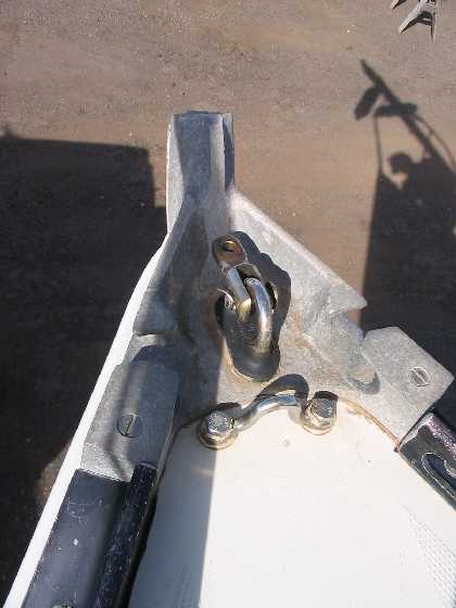
Rudder Retaining Pin
I believe that the ring
below the tiller handle on my G26 is a collar that retains the rudder from
falling out. There is a pin that goes through one side of this collar. My
guess is that if the pin falls out bye bye rudder as the tiller casting is
not meant to hold the rudder. On my boat this collar had several layers of
electrical tape preventing the pin from coming out.
Anyone have an idea how this pin was originally held in place or how theirs
is retained? (Matt)
Mine has
an oversize (length) PIN with a HOLE through each end for a RING CLIP. (Chris
Johnson)
The original factory pin
was embossed with a crisscross pattern on each end. I made up a new pin -
1/4" s/s rod - cut to exact length so when installed, it rests on a large
s/s washer that fits over the rudder shaft.
Since our rudder is removed every year and taken home for the winter (advice
from George Cassian of C&C), the pin has to be easily removed.
When remounted in the spring, we simply put some "blue locktite" on one end
of the pin, then push it into place. This pin has never come loose in over
10 years of hard racing and lots of heavy weather bashing. (Jim Quimbell)
On my G30 I
have a few brass rings under the pin. I believe these act not only as a
retainer but a bearing also. The weight of the rudder holds the pin in
place. I've had
my G30 for 20 years and the rudder is still there. (Bob Whittall)
See also General FAQ
______________________
-
Where to Position Jib Blocks
I have struggled with the placement
of my jib line block placement on my G26 from the very first day I sailed
her. I'm assuming that most G26's are set up with a single block that snaps
onto the toe rail before the line goes back to the winch.I have moved them
from the very stern to very close to the winch body but I'm still not sure
of the best placement. I guess I should tell you that I have a roller
furling with a 150 head sail.
Is there a best place to set these
blocks or is it dependent on the sailing conditions? (Jimmy Schools)
___________________
Most roller furling
jibs have a higher clew, so your solution may be different from ours.
You probably should be
setting your block eight inches in front of the winch. Bring your jib in
within three inches of your spreaders, go hard on the wind, adjust the block
fore and aft so that the sail breaks evenly on the luff - top to bottom at
the same time. Then adjust your leech line to quiet the leech.
There have been times
when we use double blocks, fore and aft. We ran a second block aft and then
to the winch when the sheet lead was too severe to the winch. Some of the
G26's have grooves worn into the fiberglass on the winch pad from the severe
sheet lead. (Leslie Hughes)
_________________________
The placement of the blocks depends
on what gives the headsail proper shape. If you have telltales on the genoa,
you can approximate proper shape by setting the block so that when you're on
a beat, telltales at the luff are flying evenly at the lower and middle
portion of the sail, and just fluttering a little at the top. The more off
the wind you go and the more you ease the genoa sheet, then ideally the more
the block should move forward to achieve even flow along the luff ( to keep
the clew from riding up and spilling wind at the top).
A rough first guess about position
for sailing to windward would be to find the point midway up the luff, and
mentally draw a line from there to the clew, and then continue that mental
line down to the toe rail. That's about where you should set the block, so
that as you sight along the sheet up to the clew the "line" continues to the
midpoint of the luff. Then you can tweak that position as you watch the
telltales. If your lower telltales are flying and not the uppers you're too
far back; if the uppers are flying and the lowers not, then you're too far
forward.
If you found a good spot that way
for the sail on a beat, then repeat that to find a spot further forward for
when the wind is just ahead of the beam, and a third spot for when the wind
is on your quarter, and you'll have things in pretty good order. If your
genoa furls, then you need to go through this again when it's in one of its
most common furled position. Of course, it's a pain to be resetting that
block a lot, but if you'll be on a particular point of sail for awhile, it's
worth it.
If the block is too far aft, you'll
be spilling wind at the top (not a bad idea in heavy air though). If it's
too far foward the sail won't draw well along most of its length.
It's
a matter of how anal you want to get about the efficiency of the genoa. I
suggest at least worrying about a best position when you're going to
windward and a second position when you're on a broad reach or running.
(Bob Hughes)
_________________________
-
Handrails
I'm looking for a
pair of teak handrails with three loops/four pads. It turns out that
Grampian had made their own which are longer than the standard ones you find
in marine stores now. I remember someone on the list mentioning they had
some new old stock, but that was a few years ago and I can't find that
message.
Before I make a
set, does anyone know where I could find these handrails? (Tim Nye)
___________________
I don't know
where to get new handrails, but I am surprised you need new ones. Mine are
in good shape despite being left without varnish for too long. What is
deteriorating is the places where the handrails are attached. Do you (or
anyone) know what is under there and how it can be repaired? (Mitch Rothman)
_____________
The deal is that
I've removed the handrails from the cabin roof and am refinishing them.
When I put them back on, instead of just handrails on the outside, I want to
put another set on the inside of the cabin ceiling to give more things to
grab onto inside the cabin.
If I can find
handrails for the inside that match the outside I can run bolts through
outside handrail, cabin roof and inside handrail to hold both on. The ends
of the holes can be counterbored and plugged so you don't see the bolts.
The mounting of
the handrails is pretty simple -- all they did was drill a hole through the
cabin roof at each pad and drive a long woodscrew up from underneath. The
cabin roof is fiberglass on the inside and outside and a balsa core. The
pads on the handrails have sealant between them and the cabin roof. If
things are getting deteriorated there it might be worthwhile to take the
handrails off and redo the sealant. If it breaks down, rainwater will get
into the balsa core and start the process of delamination and rotting.
In
fact, the survey done when we got our boat mentioned some delamination just
outboard of one of the handrails. This would have almost certainly been due
to water leaking in the screw holes. (Tim Nye)
___________________________
The outside
handrails on my G26 are slot screw from the top into the fiberglass
pads. The inside handrails are also slot screws into the pads from
inside the cabin. Neither is attached to the other as I've had both
mine off to refinish them. I like the idea of a through bolt
for better
purchase though (Sandy Piper)
______________________________
My G26 didn't
come with handrails on the inside. So I made inside rails for it. I debated
about through bolting the inside and outside hand rails but I thought that
put the inside rails to far outboard. Instead, I used the hatch slide on the
cabin top and drilled though it and the cabin top. Being a bit anal, I
suggest you drill it over sized, scrape out some coring, duct tape the
underside, fill with epoxy and redrill the right size. I then measured the
distance between the holes and fashioned some hand rails.
To fashion the
rails, I used 1.5"x 6"x6' board. You could use smaller but I liked the feel
of it. Then with a 4" hole saw centered in the board and 1" to each side of
where the bolts would be, drill away. Cut length wise though the middle of
the holes. Connect the other edge of the holes making the wood look like
handles. I just eyeballed the ends to make them rounded with a jig saw.
Now round over
all the edges and with a bit of sanding and some oil they look great (I
think). As a plus it's a great place to hang an oil lamp over the table, a
tiny bag for sail ties near the hatch and a net hammock for bread.
Installing them
was the tricky part. You'll find there are no flat surfaces on a boat. I
used a piece of card board and held it up on edge to the cabin top and kept
cutting pieces off till it would sit there flat. I then marked where the
bolts would go and transferred the pattern to the hand rail. Mine weren't
exactly the same on each side so check before you cut. It was then I needed
another body, 1 to hold the rail while the other drilled from the outside
through the rails. Once that is done, it's easy to take care of the counter
sinking but you'll need the body again when you install the bolts so don't
let them get away. I cut the plugs from the scraps. Pay attention to the
grain; I messed up one and had to drill it back out. (Earl F Hampton lll)
_____________________
-
Sloppy Rudder
Play
I have a problem
with very sloppy rudder play. (Jimmy Schools)
_____________
Have not worked on a G
26 but this method works on G 30 and several C&Cs. The boat needs to be out
of the water. Remove the rudder and clean out the shaft housing getting
all oil and grease out of it. Do a final wash with acetone. Put a very
light coating of oil, or grease on the rudder shaft.
Mix a batch of epoxy using a thickener. Do not use micro balloons. Add
graphite powder to the mixture and then using a stick or whatever. coat the
inside of the rudder shaft. Insert the rudder and prop it up into place.
Push whatever epoxy you can down from the top and up from the bottom.
Let the epoxy harden until it is in a plastic state but not completely hard
and then give the rudder a little twist. Wait a little while and twist
again. Watch that you do not let it wobble from side to side. When hard
replace thrust bearing and pin and off you go. (Jim
M)
______________________
As I understand it, the G26 had two versions of
bearing bushings in the rudder tube. The earlier ones were gunmetal (a type
of bronze)
soldered into the copper tube. The later ones were plastic that were pressed
in.
If you have the plastic already, you can drive them out and either take them
to a bearing distributor (look in your yellow pages) or try McMaster-Carr (http://www.mcmaster.com/)
under "sleeve bearings" to see if you can match something up. If you can't,
try a machine shop to see if they can machine new parts for you.
If you've got the metal bushings, it's going to be tougher because they're
soldered in. The heat required to melt the solder will destroy the
fiberglass at the hull and cockpit sole. It's possible to machine out the
old bushings and put in new plastic ones, but that's bound to be an
expensive job.
You can build up the worn bushing surfaces with an epoxy filled with a
bearing material. There's a Devcon bronze material (McMaster-Carr part
number 74575A64) but it only comes in 1 lb cans for $60. It's a putty, so
you'd have to smear it in, let it harden, then try to machine the bore
straight and round.
If it was my boat, I'd try making my own bearing repair epoxy. I'd get
graphite powder and mix it with an epoxy until it's at ketchup consistency.
The epoxy will hold the graphite in place, and the graphite will be the
bearing material.
I'd make a 'form' the same diameter as the rudder shaft to fit in the rudder
tube. For instance, get two UHMW plastic bushings with the same outside
diameter as the rudder shaft and a wood dowel to hold them aligned with each
other and space them out so they match up with the upper and lower bushing
in the stern tube. Put this form in the stern tube and there will be the
same gaps between the bushings and this form as between the bushings and
your rudder shaft.
Now get a medical syringe with a pointy needle, fill it with the
epoxy-graphite mixture and squirt it in the gaps between the bushings and
your form. I'd have different sizes of needle on hand because I don't know
how small a needle the mixture will pass through.
Once the epoxy sets take out the form. Epoxy isn't supposed to stick to UHMW
plastic, but if it does, just cut out your form. Use a file, sandpaper, etc,
to smooth out any rough edges. I haven't done this on a boat, but I've done
similar epoxy build-up jobs on worn machinery with good success in the past.
(Tim Nye)


.JPG)
.jpg)